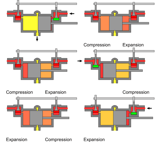
The poppet valves are controlled by the rotating camshaft at the top. High pressure steam enters, red, and exhausts, yellow.
The uniflow type of steam engine uses steam that flows in one direction only in each half of the cylinder. Thermal efficiency is increased by having a temperature gradient along the cylinder. Steam always enters at the hot ends of the cylinder and exhausts through ports at the cooler centre. By this means, the relative heating and cooling of the cylinder walls is reduced.
Design details

Steam entry is usually controlled by poppet valves (which act similarly to those used in internal combustion engines) that are operated by a camshaft. The inlet valves open to admit steam when minimum expansion volume has been reached at the start of the stroke. For a period of the crank cycle, steam is admitted, and the poppet inlet is then closed, allowing continued expansion of the steam during the stroke, driving the piston. Near the end of the stroke, the piston will uncover a ring of exhaust ports mounted radially around the centre of the cylinder. These ports are connected by a manifold and piping to the condenser, lowering the pressure in the chamber below that of the atmosphere causing rapid exhausting. Continued rotation of the crank moves the piston. From the animation, the features of a uniflow engine can be seen, with a large piston almost half the length of the cylinder, poppet inlet valves at either end, a camshaft (whose motion is derived from that of the driveshaft) and a central ring of exhaust ports.
Advantages
Uniflow engines potentially allow greater expansion in a single cylinder without the relatively cool exhaust steam flowing across the hot end of the working cylinder and steam ports of a conventional "counterflow" steam engine during the exhaust stroke. This condition allows higher thermal efficiency. The exhaust ports are open for only a small fraction of the piston stroke, with the exhaust ports closed just after the piston begins traveling toward the admission end of the cylinder. The steam remaining within the cylinder after the exhaust ports are closed is trapped, and this trapped steam is compressed by the returning piston. This is thermodynamically desirable as it preheats the hot end of the cylinder before the admission of steam. However, the risk of excessive compression often results in small auxiliary exhaust ports being included at the cylinder heads. Such a design is called a semi-uniflow engine
Engines of this type usually have multiple cylinders in an in-line arrangement, and may be single- or double-acting. A particular advantage of this type is that the valves may be operated by the effect of multiple camshafts, and by changing the relative phase of these camshafts, the amount of steam admitted may be increased for high torque at low speed, and may be decreased at cruising speed for economy of operation. Alternatively, designs using a more-complex cam surface allowed the varying of timing by shifting the entire camshaft longitudinally compared to its follower, allowing the admission timing to be varied. (The camshaft could be shifted by mechanical or hydraulic devices.) And, by changing the absolute phase, the engine's direction of rotation may be changed. The uniflow design also maintains a constant temperature gradient through the cylinder, avoiding passing hot and cold steam through the same end of the cylinder.
Disadvantages
In practice, the uniflow engine has a number of operational shortcomings. The large expansion ratio requires a large cylinder volume. To gain the maximum potential work from the engine a high reciprocation rate is required, typically 80% faster than a double-acting counterflow type engine. This causes the opening times of the inlet valves to be very short, putting great strain on a delicate mechanical part. In order to withstand the huge mechanical forces encountered, engines have to be heavily built and a large flywheel is required both to smooth out the variations in torque as the steam pressure rapidly rises and falls in the cylinder and to compensate for the inertia of the heavy piston. Because there is a thermal gradient across the cylinder, the metal of the wall expands to different extents. This requires the cylinder bore to be machined wider in the cool center (sometimes described as "egg-shaped") than at the hot ends. If the cylinder is not heated correctly, or if water enters, the delicate balance can be upset causing seizure mid-stroke and, potentially, destruction.
History
The uniflow engine was first used in Britain in 1827 by Jacob Perkins and was patented in 1885 by Leonard Jennett Todd. It was popularised by German engineer Johann Stumpf in 1909, with the first commercial stationary engine produced a year previously in 1908.
Steam locomotives
The uniflow principle was mainly used for industrial power generation, but was also tried in a few railway locomotives in England, such as the North Eastern Railway uniflow locomotives No.825 of 1913, and No.2212 of 1918, and the Midland Railway Paget locomotive. Experiments were also made in France, Germany, the United States and Russia. In no case were the results encouraging enough for further development to be undertaken.
Steam wagons

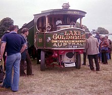
The first large-scale utilization of a Uniflow engine was in Atkinson steam wagons, in 1918. Only one such steam wagon is known to be still in existence; it was built in 1918, spent its working life and a period of dereliction in Australia, and was then repatriated to England and restored by Tom Varley in 1976-77.
Skinner Unaflow
The final commercial evolution of the uniflow engine occurred in the United States during the late 1930s and 1940s by the Skinner Engine Company with the development of the Compound Unaflow Marine Steam Engine. This engine operates in a steeple compound configuration and provides efficiencies approaching contemporary diesels. Many car ferries on the Great Lakes were so equipped, one of which is still operating, SS Badger of 1952. The Casablanca-class escort carrier, the most prolific aircraft carrier design in history, used two 5-cylinder Skinner Unaflow engines, but these were not steeple compounds. A non-compound Skinner Uniflow remained in service until 2013 in the Great Lakes cement carrier SS St. Marys Challenger, installed when the vessel was re-powered in 1950. The SS Prince George used two recycled 6 cylinder Skinner uniflows, it was retired in 1984
In small sizes (less than about 1,000 hp (750 kW)), reciprocating steam engines are much more efficient than steam turbines. White Cliffs Solar Power Station used a three-cylinder uniflow engine with "Bash"-type admission valves to generate about 25 kW electrical output.
Home-made conversions of two-stroke engines
The single-acting uniflow steam engine configuration closely resembles that of a two-stroke internal combustion engine, and it is possible to convert a two-stroke engine to a uniflow steam engine by feeding the cylinder with steam via a "bash valve" fitted in place of the spark plug. As the rising piston nears the top of its stroke, it knocks open the bash valve to admit a pulse of steam. The valve closes automatically as the piston descends, and the steam is exhausted through the existing cylinder porting. The inertia of the flywheel then carries the piston back to the top of its stroke against the compression, as it does in the original form of the engine. Also like the original, the conversion is not self-starting and must be turned over by an external power source to start. An example of such a conversion is the steam-powered moped, which is started by pedalling.
See also
References
- ^ The Museum of Retro Technology – Uniflow Steam Locomotives.
- "Haute Pression! French High-Pressure Locomotives". 2006-01-03. Retrieved 2019-10-21.
- Commercial Motor. 1918-08-15.
- Boddy, Bill (June 1977). "V-E-V Odds & Ends The Riley Register's". Motor Sport. p. 676. Retrieved 8 January 2023.
- "BBC North West Regional News Material 1973-1986: Programme Details - Further details for Look North West: Friday 22/4/1977". North West Film Archive. Retrieved 8 January 2023.
- Bash Valve - description
- Steam-powered moped
Sources
- Teach yourself heat engines by E. de Ville, published by The English Universities Press Limited, London, 1960, pp 40–41
External links
| Steam engines | |||||||||||||||||||
|---|---|---|---|---|---|---|---|---|---|---|---|---|---|---|---|---|---|---|---|
| Operating cycle | |||||||||||||||||||
| Valves |
| ||||||||||||||||||
| Mechanisms | |||||||||||||||||||
| Boilers |
| ||||||||||||||||||
| Cylinder | |||||||||||||||||||
| Condenser | |||||||||||||||||||
| Other | |||||||||||||||||||
| History |
| ||||||||||||||||||
| See also | |||||||||||||||||||