A microwave cavity or radio frequency cavity (RF cavity) is a special type of resonator, consisting of a closed (or largely closed) metal structure that confines electromagnetic fields in the microwave or RF region of the spectrum. The structure is either hollow or filled with dielectric material. The microwaves bounce back and forth between the walls of the cavity. At the cavity's resonant frequencies they reinforce to form standing waves in the cavity. Therefore, the cavity functions similarly to an organ pipe or sound box in a musical instrument, oscillating preferentially at a series of frequencies, its resonant frequencies. Thus it can act as a bandpass filter, allowing microwaves of a particular frequency to pass while blocking microwaves at nearby frequencies.
A microwave cavity acts similarly to a resonant circuit with extremely low loss at its frequency of operation, resulting in quality factors (Q factors) up to the order of 10, for copper cavities, compared to 10 for circuits made with separate inductors and capacitors at the same frequency. For superconducting cavities, quality factors up to the order of 10 are possible. They are used in place of resonant circuits at microwave frequencies, since at these frequencies discrete resonant circuits cannot be built because the values of inductance and capacitance needed are too low. They are used in oscillators and transmitters to create microwave signals, and as filters to separate a signal at a given frequency from other signals, in equipment such as radar equipment, microwave relay stations, satellite communications, and microwave ovens.
RF cavities can also manipulate charged particles passing through them by application of acceleration voltage and are thus used in particle accelerators and microwave vacuum tubes such as klystrons and magnetrons.
Theory of operation

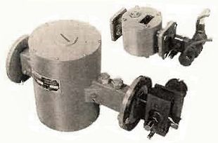
(1) A setscrew trimmer capacitor used to adjust the frequency
(2) The top of the GS13-1 (Russian: ГС-13-1) triode which generates the microwaves
(3) A wire coupling loop from which the output power is taken
Most resonant cavities are made from closed (or short-circuited) sections of waveguide or high-permittivity dielectric material (see dielectric resonator). Electric and magnetic energy is stored in the cavity. This energy decays over time due to several possible loss mechanisms.
The section on 'Physics of SRF cavities' in the article on superconducting radio frequency contains a number of important and useful expressions which apply to any microwave cavity:
The energy stored in the cavity is given by the integral of field energy density over its volume,
- ,
where:
- H is the magnetic field in the cavity and
- μ0 is the permeability of free space.
The power dissipated due just to the resistivity of the cavity's walls is given by the integral of resistive wall losses over its surface,
- ,
where:
- Rs is the surface resistance.
For copper cavities operating near room temperature, Rs is simply determined by the empirically measured bulk electrical conductivity σ see Ramo et al pp.288-289
- .
A resonator's quality factor is defined by
- ,
where:
- ω is the resonant frequency in ,
- U is the energy stored in , and
- Pd is the power dissipated in in the cavity to maintain the energy U.
Basic losses are due to finite conductivity of cavity walls and dielectric losses of material filling the cavity. Other loss mechanisms exist in evacuated cavities, for example the multipactor effect or field electron emission. Both multipactor effect and field electron emission generate copious electrons inside the cavity. These electrons are accelerated by the electric field in the cavity and thus extract energy from the stored energy of the cavity. Eventually the electrons strike the walls of the cavity and lose their energy. In superconducting radio frequency cavities there are additional energy loss mechanisms associated with the deterioration of the electric conductivity of the superconducting surface due to heating or contamination.
Every cavity has numerous resonant frequencies that correspond to electromagnetic field modes satisfying necessary boundary conditions on the walls of the cavity. Because of these boundary conditions that must be satisfied at resonance (tangential electric fields must be zero at cavity walls), at resonance, cavity dimensions must satisfy particular values. Depending on the resonance transverse mode, transverse cavity dimensions may be constrained to expressions related to geometric functions, or to zeros of Bessel functions or their derivatives (see below), depending on the symmetry properties of the cavity's shape. Alternately it follows that cavity length must be an integer multiple of half-wavelength at resonance (see page 451 of Ramo et al). In this case, a resonant cavity can be thought of as a resonance in a short circuited half-wavelength transmission line.
The external dimensions of a cavity can be made considerably smaller at its lowest frequency mode by loading the cavity with either capacitive or inductive elements. Loaded cavities usually have lower symmetries and compromise certain performance indicators, such as the best Q factor. As examples, the reentrant cavity and helical resonator are capacitive and inductive loaded cavities, respectively.
Multi-cell cavity
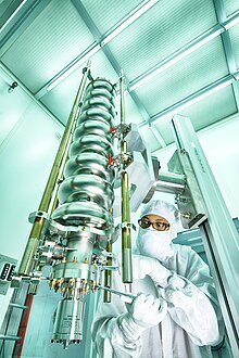
Single-cell cavities can be combined in a structure to accelerate particles (such as electrons or ions) more efficiently than a string of independent single cell cavities. The figure from the U.S. Department of Energy shows a multi-cell superconducting cavity in a clean room at Fermi National Accelerator Laboratory.

Loaded microwave cavities
A microwave cavity has a fundamental mode, which exhibits the lowest resonant frequency of all possible resonant modes. For example, the fundamental mode of a cylindrical cavity is the TM010 mode. For certain applications, there is motivation to reduce the dimensions of the cavity. This can be done by using a loaded cavity, where a capacitive or an inductive load is integrated in the cavity's structure.
The precise resonant frequency of a loaded cavity must be calculated using finite element methods for Maxwell's equations with boundary conditions.
Loaded cavities (or resonators) can also be configured as multi-cell cavities.
Loaded cavities are particularly suited for accelerating low velocity charged particles. This application for many types of loaded cavities, Some common types are listed below.
- The reentrant cavity
- The helical resonator

- The spiral resonator
- The split-ring resonator

- The quarter wave resonator
- The half wave resonator. A variant of the half-wave resonator is the spoke resonator.
- The Radio-frequency quadrupole

.
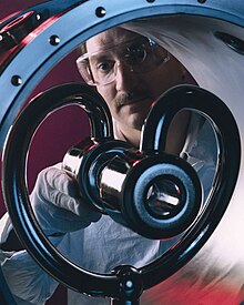
- Compact Crab cavity. Compact crab cavities are an important upgrade for the LHC.
The Q factor of a particular mode in a resonant cavity can be calculated. For a cavity with high degrees of symmetry, using analytical expressions of the electric and magnetic field, surface currents in the conducting walls and electric field in dielectric lossy material. For cavities with arbitrary shapes, finite element methods for Maxwell's equations with boundary conditions must be used. Measurement of the Q of a cavity are done using a Vector Network analyzer (electrical), or in the case of a very high Q by measuring the exponential decay time of the fields, and using the relationship .
The electromagnetic fields in the cavity are excited via external coupling. An external power source is usually coupled to the cavity by a small aperture, a small wire probe or a loop, see page 563 of Ramo et al. External coupling structure has an effect on cavity performance and needs to be considered in the overall analysis, see Montgomery et al page 232.
Resonant frequencies
The resonant frequencies of a cavity are a function of its geometry.
Rectangular cavity

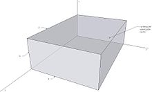
Resonance frequencies of a rectangular microwave cavity for any or resonant mode can be found by imposing boundary conditions on electromagnetic field expressions. This frequency is given at page 546 of Ramo et al:
| 1 |
where is the wavenumber, with , , being the mode numbers and , , being the corresponding dimensions; c is the speed of light in vacuum; and and are relative permeability and permittivity of the cavity filling respectively.
Cylindrical cavity

The field solutions of a cylindrical cavity of length and radius follow from the solutions of a cylindrical waveguide with additional electric boundary conditions at the position of the enclosing plates. The resonance frequencies are different for TE and TM modes.
- TM modes
See Jackson
| 2a |
- TE modes
See Jackson
| 2b |
Here, denotes the -th zero of the -th Bessel function, and denotes the -th zero of the derivative of the -th Bessel function. and are relative permeability and permittivity respectively.
Quality factor
The quality factor of a cavity can be decomposed into three parts, representing different power loss mechanisms.
- , resulting from the power loss in the walls which have finite conductivity. The Q of the lowest frequency mode, or "fundamental mode" are calculated, see pp. 541-551 in Ramo et al for a rectangular cavity (Equation 3a) with dimensions and parameters , and the mode of a cylindrical cavity (Equation 3b) with parameters as defined above.
| 3a |
| 3b |
where is the intrinsic impedance of the dielectric, is the surface resistivity of the cavity walls. Note that .
- , resulting from the power loss in the lossy dielectric material filling the cavity, where is the loss tangent of the dielectric
| 4 |
- , resulting from power loss through unclosed surfaces (holes) of the cavity geometry.
Total Q factor of the cavity can be found as in page 567 of Ramo et al
| 5 |
Comparison to LC circuits

Microwave resonant cavities can be represented and thought of as simple LC circuits, see Montgomery et al pages 207-239. For a microwave cavity, the stored electric energy is equal to the stored magnetic energy at resonance as is the case for a resonant LC circuit. In terms of inductance and capacitance, the resonant frequency for a given mode can be written as given in Montgomery et al page 209
| 6 |
| 7 |
| 8 |
where V is the cavity volume, is the mode wavenumber and and are permittivity and permeability respectively.
To better understand the utility of resonant cavities at microwave frequencies, it is useful to note that conventional inductors and capacitors start to become impractically small with frequency in the VHF, and definitely so for frequencies above one gigahertz. Because of their low losses and high Q factors, cavity resonators are preferred over conventional LC and transmission-line resonators at high frequencies.
Losses in LC resonant circuits

Conventional inductors are usually wound from wire in the shape of a helix with no core. Skin effect causes the high frequency resistance of inductors to be many times their direct current resistance. In addition, capacitance between turns causes dielectric losses in the insulation which coats the wires. These effects make the high frequency resistance greater and decrease the Q factor.
Conventional capacitors use air, mica, ceramic or perhaps teflon for a dielectric. Even with a low loss dielectric, capacitors are also subject to skin effect losses in their leads and plates. Both effects increase their equivalent series resistance and reduce their Q.
Even if the Q factor of VHF inductors and capacitors is high enough to be useful, their parasitic properties can significantly affect their performance in this frequency range. The shunt capacitance of an inductor may be more significant than its desirable series inductance. The series inductance of a capacitor may be more significant than its desirable shunt capacitance. As a result, in the VHF or microwave regions, a capacitor may appear to be an inductor and an inductor may appear to be a capacitor. These phenomena are better known as parasitic inductance and parasitic capacitance.
Losses in cavity resonators
Dielectric loss of air is extremely low for high-frequency electric or magnetic fields. Air-filled microwave cavities confine electric and magnetic fields to the air spaces between their walls. Electric losses in such cavities are almost exclusively due to currents flowing in cavity walls. While losses from wall currents are small, cavities are frequently plated with silver to increase their electrical conductivity and reduce these losses even further. Copper cavities frequently oxidize, which increases their loss. Silver or gold plating prevents oxidation and reduces electrical losses in cavity walls. Even though gold is not quite as good a conductor as copper, it still prevents oxidation and the resulting deterioration of Q factor over time. However, because of its high cost, it is used only in the most demanding applications.
Some satellite resonators are silver-plated and covered with a gold flash layer. The current then mostly flows in the high-conductivity silver layer, while the gold flash layer protects the silver layer from oxidizing.
References
- Лампа генераторная ГС-13-1. eandc.ru (in Russian). Retrieved 2022-04-20.
- ^ Simon Ramo, John Roy Whinnery, Theodore Van Duzer (1965). Fields and Waves in Communication Electronics. John Wiley and Sons.
- ^ Ilan Ben-Zvi, Peter H. Ceperley and H. A. Schwettman, "The Design of Re-Entrant Cavities", Particle Accelerators. 1976, Vol. 7, pp. 125-135, https://cds.cern.ch/record/1021070/files/p125.pdf
- https://uspas.fnal.gov/materials/11ODU/Proton_5.pdf
- Carter, Richard G.; Feng, Jinjun; Becker, Ulrich (2007). "Calculation of the Properties of Reentrant Cylindrical Cavity Resonators" (PDF). IEEE Transactions on Microwave Theory and Techniques. 55 (12): 2531–2538 – via IEEE Xplore.
- E. Jaeschke et al., "The Heidelberg 3MV-CW Heavy Ion Postaccelerator Section Using Independently Phased Spiral Resonators" in IEEE Transactions on Nuclear Science, vol. 24, no. 3, pp. 1136-1140, June 1977, doi: 10.1109/TNS.1977.4328874.
- K. W. Shepard, J. E. Mercereau and G. J. Dick, "A New Superconducting Heavy Ion Accelerating Structure Using Chemically Polished Lead Surfaces," in IEEE Transactions on Nuclear Science, vol. 22, no. 3, pp. 1179-1182, June 1975, doi: 10.1109/TNS.1975.4327840.
- Ben-Zvi, I.; Brennan, J. M. (1983-07-01). "The quarter wave resonator as a superconducting linac element". Nuclear Instruments and Methods in Physics Research. 212 (1): 73–79. Bibcode:1983NIMPR.212...73B. doi:10.1016/0167-5087(83)90678-6. ISSN 0167-5087.
- Delayen, J. R., and J. E. Mercereau. "Cryogenic test of a superconducting half-wave resonator for the acceleration of heavy ions." Nuclear Instruments and Methods in Physics Research Section A: Accelerators, Spectrometers, Detectors and Associated Equipment 257.2 (1987): 71-76.
- https://accelconf.web.cern.ch/abdwhb06/PAPERS/THAY07.PDF
- https://www.osti.gov/servlets/purl/10143844
- Design and vertical tests of double-quarter wave cavity prototypes for the high-luminosity LHC crab cavity system, Design and vertical tests of double-quarter wave cavity prototypes for the high-luminosity LHC crab cavity system S. Verdú-Andr´es et al, Physical Review Accelerators and Beams, 21, 082002 (2018)
- https://cds.cern.ch/record/2846160/files/document.pdf
- John C. Slater (1969). Microwave Electronics. Dover Publications. New York. Chapter IV p. 69.
- ^ Montgomery, C. G. & Robert H. Dicke & Edward Mills Purcell, Principles of microwave circuits / edited by C.G. Montgomery, R.H. Dicke, E.M. Purcell, Peter Peregrinus on behalf of the Institution of Electrical Engineers, London, U.K., 1987.
- ^ John David Jackson (physicist), Classical Electrodynamics, Wiley (1967) pp.254-255
External links
- Cavity Resonators, The Feynman Lectures on Physics Vol. II Ch. 23
- Crab cavity for the LHC
 ,
, ,
, .
. ,
, of the fields, and using the relationship
  .
.


 is the
  ,
,  ,
,  being the mode numbers and
  ,
,  ,
,  being the corresponding dimensions; c is the speed of light in vacuum; and
  and
and  are relative
  and radius
  follow from the solutions of a cylindrical

 denotes the
  denotes the
  of a cavity can be decomposed into three parts, representing different power loss mechanisms.
 , resulting from the power loss in the walls which have finite conductivity. The Q of the lowest frequency mode, or "fundamental mode" are calculated, see pp. 541-551 in Ramo et al for a rectangular cavity (Equation 3a) with dimensions
  and parameters
  , and the
  mode of a cylindrical cavity (Equation 3b) with parameters
  as defined above.

 is the
  is the
  .
.
 , resulting from the power loss in the lossy
  is the
 , resulting from power loss through unclosed surfaces (holes) of the cavity geometry.
 mode can be written as given in Montgomery et al page 209


 and
and  are permittivity and permeability respectively.