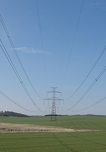
In physics and electrical engineering, a conductor is an object or type of material that allows the flow of charge (electric current) in one or more directions. Materials made of metal are common electrical conductors. The flow of negatively charged electrons generates electric current, positively charged holes, and positive or negative ions in some cases.
In order for current to flow within a closed electrical circuit, one charged particle does not need to travel from the component producing the current (the current source) to those consuming it (the loads). Instead, the charged particle simply needs to nudge its neighbor a finite amount, who will nudge its neighbor, and on and on until a particle is nudged into the consumer, thus powering it. Essentially what is occurring is a long chain of momentum transfer between mobile charge carriers; the Drude model of conduction describes this process more rigorously. This momentum transfer model makes metal an ideal choice for a conductor; metals, characteristically, possess a delocalized sea of electrons which gives the electrons enough mobility to collide and thus affect a momentum transfer.
As discussed above, electrons are the primary mover in metals; however, other devices such as the cationic electrolyte(s) of a battery, or the mobile protons of the proton conductor of a fuel cell rely on positive charge carriers. Insulators are non-conducting materials with few mobile charges that support only insignificant electric currents.
Resistance and conductance

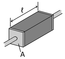
The resistance of a given conductor depends on the material it is made of, and on its dimensions. For a given material, the resistance is inversely proportional to the cross-sectional area. For example, a thick copper wire has lower resistance than an otherwise-identical thin copper wire. Also, for a given material, the resistance is proportional to the length; for example, a long copper wire has higher resistance than an otherwise-identical short copper wire. The resistance R and conductance G of a conductor of uniform cross section, therefore, can be computed as
where is the length of the conductor, measured in metres , A is the cross-section area of the conductor measured in square metres , σ (sigma) is the electrical conductivity measured in siemens per meter (S·m), and ρ (rho) is the electrical resistivity (also called specific electrical resistance) of the material, measured in ohm-metres (Ω·m). The resistivity and conductivity are proportionality constants, and therefore depend only on the material the wire is made of, not the geometry of the wire. Resistivity and conductivity are reciprocals: . Resistivity is a measure of the material's ability to oppose electric current.
This formula is not exact: It assumes the current density is totally uniform in the conductor, which is not always true in practical situation. However, this formula still provides a good approximation for long thin conductors such as wires.
Another situation this formula is not exact for is with alternating current (AC), because the skin effect inhibits current flow near the center of the conductor. Then, the geometrical cross-section is different from the effective cross-section in which current actually flows, so the resistance is higher than expected. Similarly, if two conductors are near each other carrying AC current, their resistances increase due to the proximity effect. At commercial power frequency, these effects are significant for large conductors carrying large currents, such as busbars in an electrical substation, or large power cables carrying more than a few hundred amperes.
Aside from the geometry of the wire, temperature also has a significant effect on the efficacy of conductors. Temperature affects conductors in two main ways, the first is that materials may expand under the application of heat. The amount that the material will expand is governed by the thermal expansion coefficient specific to the material. Such an expansion (or contraction) will change the geometry of the conductor and therefore its characteristic resistance. However, this effect is generally small, on the order of 10. An increase in temperature will also increase the number of phonons generated within the material. A phonon is essentially a lattice vibration, or rather a small, harmonic kinetic movement of the atoms of the material. Much like the shaking of a pinball machine, phonons serve to disrupt the path of electrons, causing them to scatter. This electron scattering will decrease the number of electron collisions and therefore will decrease the total amount of current transferred.
Conductor materials
Main article: Electrical resistivity and conductivity Further information: Copper conductor and Aluminum building wiring| Material | ρ at 20 °C | σ at 20 °C |
|---|---|---|
| Silver, Ag | 1.59 × 10 | 6.30 × 10 |
| Copper, Cu | 1.68 × 10 | 5.96 × 10 |
| Aluminum, Al | 2.82 × 10 | 3.50 × 10 |
Conduction materials include metals, electrolytes, superconductors, semiconductors, plasmas and some nonmetallic conductors such as graphite and conductive polymers.
Copper has a high conductivity. Annealed copper is the international standard to which all other electrical conductors are compared; the International Annealed Copper Standard conductivity is 58 MS/m, although ultra-pure copper can slightly exceed 101% IACS. The main grade of copper used for electrical applications, such as building wire, motor windings, cables and busbars, is electrolytic-tough pitch (ETP) copper (CW004A or ASTM designation C100140). If high conductivity copper must be welded or brazed or used in a reducing atmosphere, then oxygen-free high conductivity copper (CW008A or ASTM designation C10100) may be used. Because of its ease of connection by soldering or clamping, copper is still the most common choice for most light-gauge wires.
Silver is 6% more conductive than copper, but due to cost it is not practical in most cases. However, it is used in specialized equipment, such as satellites, and as a thin plating to mitigate skin effect losses at high frequencies. Famously, 14,700 short tons (13,300 t) of silver on loan from the United States Treasury were used in the making of the calutron magnets during World War II due to wartime shortages of copper.
Aluminum wire is the most common metal in electric power transmission and distribution. Although only 61% of the conductivity of copper by cross-sectional area, its lower density makes it twice as conductive by mass. As aluminum is roughly one-third the cost of copper by weight, the economic advantages are considerable when large conductors are required.
The disadvantages of aluminum wiring lie in its mechanical and chemical properties. It readily forms an insulating oxide, making connections heat up. Its larger coefficient of thermal expansion than the brass materials used for connectors causes connections to loosen. Aluminum can also "creep", slowly deforming under load, which also loosens connections. These effects can be mitigated with suitably designed connectors and extra care in installation, but they have made aluminum building wiring unpopular past the service drop.
Organic compounds such as octane, which has 8 carbon atoms and 18 hydrogen atoms, cannot conduct electricity. Oils are hydrocarbons, since carbon has the property of tetracovalency and forms covalent bonds with other elements such as hydrogen, since it does not lose or gain electrons, thus does not form ions. Covalent bonds are simply the sharing of electrons. Hence, there is no separation of ions when electricity is passed through it. Liquids made of compounds with only covalent bonds cannot conduct electricity. Certain organic ionic liquids, by contrast, can conduct an electric current.
While pure water is not an electrical conductor, even a small portion of ionic impurities, such as salt, can rapidly transform it into a conductor.
Wire size
Wires are measured by their cross sectional area. In many countries, the size is expressed in square millimetres. In North America, conductors are measured by American wire gauge for smaller ones, and circular mils for larger ones.
Conductor ampacity
The ampacity of a conductor, that is, the amount of current it can carry, is related to its electrical resistance: a lower-resistance conductor can carry a larger value of current. The resistance, in turn, is determined by the material the conductor is made from (as described above) and the conductor's size. For a given material, conductors with a larger cross-sectional area have less resistance than conductors with a smaller cross-sectional area.
For bare conductors, the ultimate limit is the point at which power lost to resistance causes the conductor to melt. Aside from fuses, most conductors in the real world are operated far below this limit, however. For example, household wiring is usually insulated with PVC insulation that is only rated to operate to about 60 °C, therefore, the current in such wires must be limited so that it never heats the copper conductor above 60 °C, causing a risk of fire. Other, more expensive insulation such as Teflon or fiberglass may allow operation at much higher temperatures.
Isotropy
If an electric field is applied to a material, and the resulting induced electric current is in the same direction, the material is said to be an isotropic electrical conductor. If the resulting electric current is in a different direction from the applied electric field, the material is said to be an anisotropic electrical conductor.
See also
| εr″/εr′ | Current conduction | Field propagation |
|---|---|---|
| 0 | perfect dielectric lossless medium | |
| ≪ 1 | low-conductivity material poor conductor |
low-loss medium good dielectric |
| ≈ 1 | lossy conducting material | lossy propagation medium |
| ≫ 1 | high-conductivity material good conductor |
high-loss medium poor dielectric |
| ∞ | perfect conductor |
- Bundle conductor
- Charge transfer complex
- Electrical cable
- Electrical resistivity and conductivity
- Fourth rail
- Overhead line
- Stephen Gray, first to identify electrical conductors and insulators
- Superconductivity
- Third rail
References
- ^ "Wire Sizes and Resistance" (PDF). Retrieved 2018-01-14.
- Fink and Beaty, Standard Handbook for Electrical Engineers 11th Edition, pages 17–19
- "High conductivity coppers (electrical)". Copper Development Association (U.K.). Archived from the original on 2013-07-20. Retrieved 2013-06-01.
- "From Treasury Vault to the Manhattan Project" (PDF). American Scientist. Retrieved 2022-10-27.
Further reading
Pioneering and historical books
- William Henry Preece. On Electrical Conductors. 1883.
- Oliver Heaviside. Electrical Papers. Macmillan, 1894.
Reference books
- Annual Book of ASTM Standards: Electrical Conductors. American Society for Testing and Materials. (every year)
- IET Wiring Regulations. Institution for Engineering and Technology. wiringregulations.net Archived 2021-04-02 at the Wayback Machine
External links
- BBC: Key Stage 2 Bitesize: Electrical Conductors
- The discovery of conductors and insulators by Gray, Dufay and Franklin.


 is the length of the conductor, measured in
  . Resistivity is a measure of the material's ability to oppose electric current.