
The Apollo spacecraft was composed of three parts designed to accomplish the American Apollo program's goal of landing astronauts on the Moon by the end of the 1960s and returning them safely to Earth. The expendable (single-use) spacecraft consisted of a combined command and service module (CSM) and an Apollo Lunar Module (LM). Two additional components complemented the spacecraft stack for space vehicle assembly: a spacecraft–LM adapter (SLA) designed to shield the LM from the aerodynamic stress of launch and to connect the CSM to the Saturn launch vehicle and a launch escape system (LES) to carry the crew in the command module safely away from the launch vehicle in the event of a launch emergency.
The design was based on the lunar orbit rendezvous approach: two docked spacecraft were sent to the Moon and went into lunar orbit. While the LM separated and landed, the CSM remained in orbit. After the lunar excursion, the two craft rendezvoused and docked in lunar orbit, and the CSM returned the crew to Earth. The command module was the only part of the space vehicle that returned with the crew to the Earth's surface.
The LES was jettisoned during launch upon reaching the point where it was no longer needed, and the SLA remained attached to the launch vehicle's upper stage. Two uncrewed CSMs, one uncrewed LM, and one crewed CSM were carried into space by Saturn IB launch vehicles for low Earth orbit Apollo missions. Larger Saturn Vs launched two uncrewed CSMs on high Earth orbit test flights, the CSM on one crewed lunar mission, the complete spacecraft on one crewed low Earth orbit mission, and eight crewed lunar missions. After conclusion of the Apollo program, four CSMs were launched on Saturn IBs for three Skylab Earth orbital missions and the Apollo-Soyuz Test Project.
Command and service module
Main article: Apollo command and service moduleThe major part of the Apollo spacecraft was a three-man vehicle designed for Earth orbital, translunar, and lunar orbital flight, and return to Earth. This consisted of a command module supported by a service module, built by North American Aviation (later North American Rockwell).
Command module (CM)

The command module was the control center for the Apollo spacecraft and living quarters for the three crewmen. It contained the pressurized main crew cabin, crew couches, control and instrument panel, Primary Guidance, Navigation and Control System, communications systems, environmental control system, batteries, heat shield, reaction control system to provide attitude control, forward docking hatch, side hatch, five windows, and a parachute recovery system. It was the only part of the Apollo/Saturn space vehicle that returned to Earth intact.
Service module (SM)

The service module was unpressurized and contained a main service propulsion engine and hypergolic propellant to enter and leave lunar orbit, a reaction control system to provide attitude control and translational capability, fuel cells with hydrogen and oxygen reactants, radiators to dump waste heat into space, and a high gain antenna. The oxygen was also used for breathing, and the fuel cells produced water for drinking and environmental control. On Apollo 15, 16 and 17 it also carried a scientific instrument package, with a mapping camera and a small sub-satellite to study the Moon.
A major portion of the service module was taken up by propellant and the main rocket engine. Capable of multiple restarts, this engine placed the Apollo spacecraft into and out of lunar orbit, and was used for mid-course corrections between the Earth and the Moon.
The service module remained attached to the command module throughout the mission. It was jettisoned just prior to reentry into the Earth's atmosphere.
Lunar Module (LM)
Main article: Apollo Lunar Module
The Apollo Lunar Module was a separate vehicle designed to land on the Moon and return to lunar orbit, and was the first true "spaceship" since it flew solely in the vacuum of space. It consisted of a descent stage and an ascent stage. It supplied life support systems for two astronauts for up to four to five days on the Apollo 15, 16 and 17 missions. The spacecraft was designed and manufactured by the Grumman Aircraft Company.
The descent stage contained the landing gear, landing radar antenna, descent propulsion system, and fuel to land on the Moon. It also had several cargo compartments used to carry, among other things: the Apollo Lunar Surface Experiment Packages ALSEP, the modularized equipment transporter (MET) (a hand-pulled equipment cart used on Apollo 14), the Lunar Rover (Apollo 15, 16 and 17), a surface television camera, surface tools, and lunar sample collection boxes.
The ascent stage contained the crew cabin, instrument panels, overhead hatch/docking port, forward hatch, optical and electronic guidance systems, reaction control system, radar and communications antennas, ascent rocket engine and propellant to return to lunar orbit and rendezvous with the Apollo Command and Service Modules.
Spacecraft–lunar module adapter (SLA)

The spacecraft–LM adapter (SLA), built by North American Aviation (Rockwell), was a conical aluminum structure that connected the service module to the Saturn S-IVB rocket stage. It also protected the LM, the service propulsion system engine nozzle, and the launch-vehicle-to-service-module umbilical during launch and ascent through the atmosphere.
The SLA was composed of four fixed 7-foot-tall (2.1 m) panels bolted to the Instrument Unit on top of the S-IVB stage, which were connected via hinges to four 21-foot-tall (6.4 m) panels which opened from the top similar to flower petals.
The SLA was made from 1.7-inch-thick (43 mm) aluminum honeycomb material. The exterior of the SLA was covered by a thin (0.03–0.2 in or 0.76–5.08 mm) layer of cork and painted white to minimize thermal stresses during ascent.
The service module was bolted to a flange at the top of the longer panels, and power to the SLA multiply-redundant pyrotechnics was provided by an umbilical. Because a failure to separate from the S-IVB stage could leave the crew stranded in orbit, the separation system used multiple signal paths, multiple detonators and multiple explosive charges where the detonation of one charge would set off another even if the detonator on that charge failed to function.

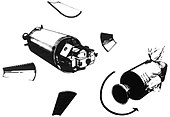
 Adapter panels are jettisoned and the CSM is turned 180 degrees
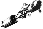
 The CSM docks with the LM and pulls it away from the Saturn V third stage.
Once in space, the astronauts pressed the 'CSM/LV Sep' button on the control panel to separate the CSM from the launch vehicle. Detonating cord was ignited around the flange between the SM and SLA, and along the joints between the four SLA panels, releasing the SM and blowing apart the connections between the panels. Dual-redundant pyrotechnic thrusters at the lower end of the SLA panels then fired to rotate them around the hinges at 30–60 degrees per second.

On all flights through Apollo 7, the SLA panels remained hinged to the S-IVB and opened to a 45-degree angle, as originally designed. But as the Apollo 7 crew practiced rendezvous with the S-IVB/SLA containing a dummy docking target, one panel did not open to the full 45 degrees, raising concern about the possibility of collision between the spacecraft and the SLA panels during docking and extraction of the LM in a lunar mission. Wally Schirra compared it to the "angry alligator" from Gemini 9. This led to a redesign using a spring-loaded hinge release system which released the panels at the 45-degree angle and pushed them away from the S-IVB at a velocity of about 5 mph (8 km/h), putting them a safe distance away by the time the astronauts pulled the CSM away, rotated it through 180 degrees, and came back for docking.
The LM was connected to the SLA at four points around the lower panels. After the astronauts docked the CSM to the LM, they blew charges to separate those connections and a guillotine severed the LM-to-instrument-unit umbilical. After the charges fired, springs pushed the LM away from the S-IVB, and the astronauts were free to continue their trip to the Moon.
Specifications
- Height: 28 ft (8.5 m)
- Apex diameter: 12 ft 10 in (3.91 m) Service module end
- Base diameter: 21 ft 8 in (6.60 m) S-IVB end
- Weight: 4,050 lb (1,840 kg)
- Volume: 6,700 cu ft (190 m), 4,900 cu ft (140 m) usable
Launch escape system (LES)

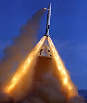
The Apollo launch escape system (LES) was built by the Lockheed Propulsion Company. Its purpose was to abort the mission by pulling the CM (the crew cabin) away from the launch vehicle in an emergency, such as a pad fire before launch, guidance failure, or launch vehicle failure likely to lead to an imminent explosion.
The LES included three wires that ran down the exterior of the launch vehicle. If the signals from any two of the wires were lost, the LES would activate automatically. Alternatively, the Commander could activate the system manually using one of two translation controller handles, which were switched to a special abort mode for launch. When activated, the LES would fire a solid fuel escape rocket and open a canard system to direct the CM away from, and off the path of, a launch vehicle in trouble. The LES would then jettison and the CM would land with its parachute recovery system.
If the emergency happened on the launch pad, the LES would lift the CM to a sufficient height to allow the recovery parachutes to deploy safely before coming in contact with the ground.
In the absence of an emergency, the LES was routinely jettisoned about 20 or 30 seconds after the launch vehicle's second-stage ignition, using a separate solid-fuel rocket motor manufactured by the Thiokol Chemical Company. Abort modes after this point would be accomplished without the LES. The LES was carried but never used on four uncrewed Apollo flights, and fifteen crewed Apollo, Skylab, and Apollo-Soyuz Test Project flights.
Major components

- Nose cone and Q-ball
- The nose cone of the LES contained an array of 8 pressure-measuring pitot tubes in a structure known as the "Q-ball". These sensors were connected to the CM and Saturn launch vehicle guidance computers, allowing calculation of dynamic pressure (q) during atmospheric flight and also the angle of attack in the event of an abort.
- Q-ball cover
- A styrofoam cover, removed a few seconds before launch, protected the pitot tubes from being clogged by debris. The cover was split in half vertically and held together by a 2-inch (51 mm) rubber band. A razor blade was positioned behind the rubber band, pinched between the halves of the cover. A wire cable was connected to the top and bottom of the razor blade and to both halves of the cover. The cable was routed through a pulley on the hammerhead crane at the top of the launch umbilical tower (LUT) down to a tube on the right side of the 360-foot (110 m) level of the LUT. The cable was connected to a cylindrical weight inside a tube. The weight rested on a lever controlled by a pneumatic solenoid valve. When the valve was actuated from the Launch Control Center (LCC), the pneumatic pressure of 600 psi (4,100 kPa) GN2 (nitrogen gas) rotated the lever down allowing the weight to drop down the tube. The dropping weight pulled the cable, which pulled the blade cutting the rubber band, and the cable pulled the halves of the cover away from the launch vehicle. The apparent overengineering of this safety system was due to the fact that the launch escape system, which depended on the Q-ball data, was armed 5 minutes before launch, so retraction of the Q-ball cover was a life-critical part of a possible pad abort.
- Canard assembly and pitch motor
- These worked in combination to direct the CM off a straight path and to the side during an emergency. This would direct the CM off the flight path of an exploding launch vehicle. It would also direct the CM to land off to the side of any launch pad fire and not in the middle of it.
- Launch escape motor
- The main solid-fuel rocket motor inside a long tube, with four exhaust nozzles mounted under a conical fairing. This would pull the CM rapidly away from a launch emergency.
- Tower jettison motor
- A smaller solid fuel motor with two exhaust nozzles, mounted in the tube, above the escape motor. This jettisoned the entire Launch Escape System after it was no longer needed, sometime after second stage ignition.
- Launch escape tower
- A truss framework of tubes that attached the escape motor fairing to the CM.
- Boost protective cover
- A hollow conical fiberglass structure protecting the CM's parachute compartment and providing a smooth aerodynamic cover over the docking tunnel and probe. After erosion of the pilot's windows from the escape motor exhaust was discovered during early LES flight testing, an aft protective cover surrounding the CM's entire upper surface was added.
Specifications
- Length minus BPC: 32 ft 6 in (9.92 m)
- Length with BPC: 39 ft 5 in (12.02 m)
- Diameter: 2 ft 2 in (0.66 m)
- Total mass: 9,200 pounds (4,200 kg)
- Thrust, 36,000 ft: 147,000 pounds-force (650 kN)
- Thrust, maximum: 200,000 pounds-force (890 kN)
- Burn time: 4.0 seconds
Abort tests
- Pad Abort Test 1 – LES abort test from launch pad with Apollo boilerplate BP-6
- Pad Abort Test 2 – LES pad abort test of near Block-I CM with Apollo boilerplate B-23A
- Little Joe II – Four in-flight LES abort tests.
Current locations of spacecraft
The disposition of all command modules, and all unflown service modules is listed at Apollo command and service module#CSMs produced. All flown service modules burned up in the Earth's atmosphere at termination of the missions. The disposition of all lunar modules is listed at Apollo Lunar Module#Lunar modules produced.
References
- No CSM was carried on the Apollo 5 uncrewed LM flight, and an aerodynamic nose cone was fastened to the top of the SLA instead.
- NASA.gov
- Launius, Roger D. "Moonport, Ch20-3". Archived from the original on July 14, 2019. Retrieved October 11, 2016.
- "Apollo Launch Abort System Test" on YouTube
- "Apollo 16 Flight Journal: Day 1 Part One". Archived from the original on July 2, 2013. Retrieved October 11, 2016.
- NASA.gov
- North American Rockwell, 'Apollo Command Module News Reference', 1968.
- NASA TN D-7083: Launch Escape Propulsion Subsystem
- Apollo Operations Handbook Lunar Module Subsystems Data
External links
- NASA report JSC-03600 Apollo/Skylab ASTP and Shuttle Orbiter Major End Items, Final Report, March 1978; NASA report listing dispositions of all rockets and spacecraft used in the Apollo, Skylab, Apollo-Soyez Test Project and early shuttle missions, as of 1978.
- Apollo D-2 Proposal by General Electric, Encyclopedia Astronautica
| Apollo program hardware | |
|---|---|
| Launch vehicles | |
| Launch vehicle components | |
| Spacecraft | |
| Spacecraft components | |
| Space suits | |
| Lunar surface equipment |
|
| Ground support | |
| Ceremonial | |
| Related | |
| Apollo program | |||||||||||
|---|---|---|---|---|---|---|---|---|---|---|---|
| Launch complexes |  | ||||||||||
| Ground facilities | |||||||||||
| Launch vehicles | |||||||||||
| Spacecraft and rover | |||||||||||
| Flights |
| ||||||||||
| Apollo 8 specific | |||||||||||
| Apollo 11 specific | |||||||||||
| Apollo 12 specific | |||||||||||
| Apollo 13 specific | |||||||||||
| Apollo 14 specific | |||||||||||
| Apollo 15 specific | |||||||||||
| Apollo 16 specific | |||||||||||
| Apollo 17 specific | |||||||||||
| Post-Apollo capsule use | |||||||||||
| Related | |||||||||||
| |||||||||||
| Crewed spacecraft (programs) | |
|---|---|
| Active |
|
| Retired |
|
| In development |
|
| Cancelled |
|